
 Deutsch
 Dansk
 Suomi
 Latviešu
 Lietuvių
 Norsk bokmål
 polski
 Русский
 Svenska

No products in the cart.
Uncategorized
Eastron SDM630MCT Smart Meter: Smart EV Load Control
11
Nov
Nov
EV load control begins with measurement, not guesswork. The Eastron SDM630MCT smart meter measures electrical values through current transformers and can transmit readings over RS485. A compatible energy-management system can use those readings as input for EV load control; the meter measures, while the system’s control logic determines how charging responds.
It’s easy to assume a smart meter directly controls a charger’s power, but its role is usually to provide data for a separate control system. Understanding this distinction helps you assess whether the meter suits your setup and what else the control system needs.
This guide explains what the Eastron SDM630MCT does, how its measurements can support EV load control, and which communication and system-compatibility details matter. You’ll get a practical view of where the meter fits, what it can contribute, and how to connect your charging requirements with suitable EV charging hardware.
Key Takeaways
- Learn what the meter measures and how its readings can inform EV charging decisions.
- Understand why the meter needs a compatible energy-management system to support load control.
- See which communication and setup details matter when assessing a potential installation.
- Explore EV charger options that can help match charging hardware to your requirements.
Eastron sdm630mct Smart Meter
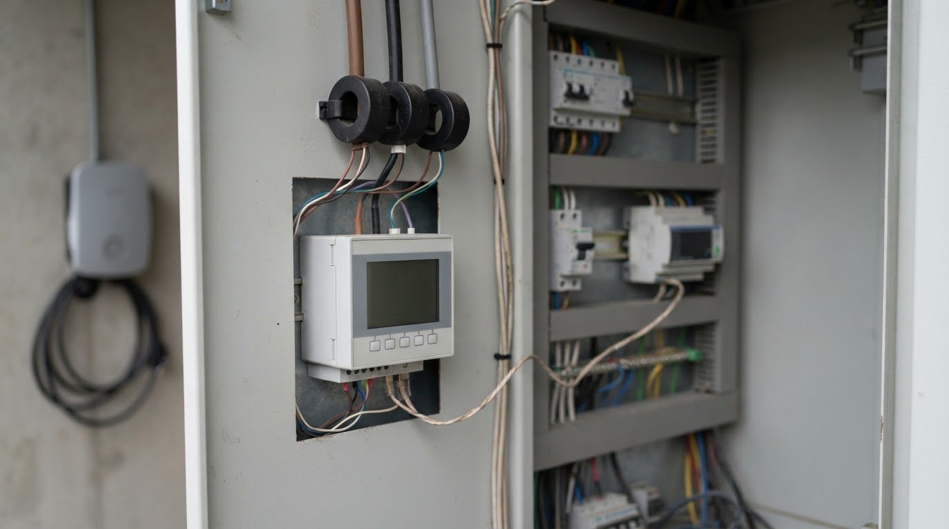
The Eastron SDM630MCT smart meter measures electrical conditions using current transformers, or CTs. A CT senses current around a conductor and sends a reduced signal to the meter. The meter then provides readings that a compatible energy-management controller can use when managing EV charging. It measures and communicates; the controller applies the load-control logic.
A meter alone doesn’t decide when an EV charges or adjust a charger’s output. For load control, its readings must reach a compatible system that can interpret them and communicate with the charging equipment. Think of the meter as the measurement link in a wider setup, not a standalone charger controller.
CT inputs and electrical systems
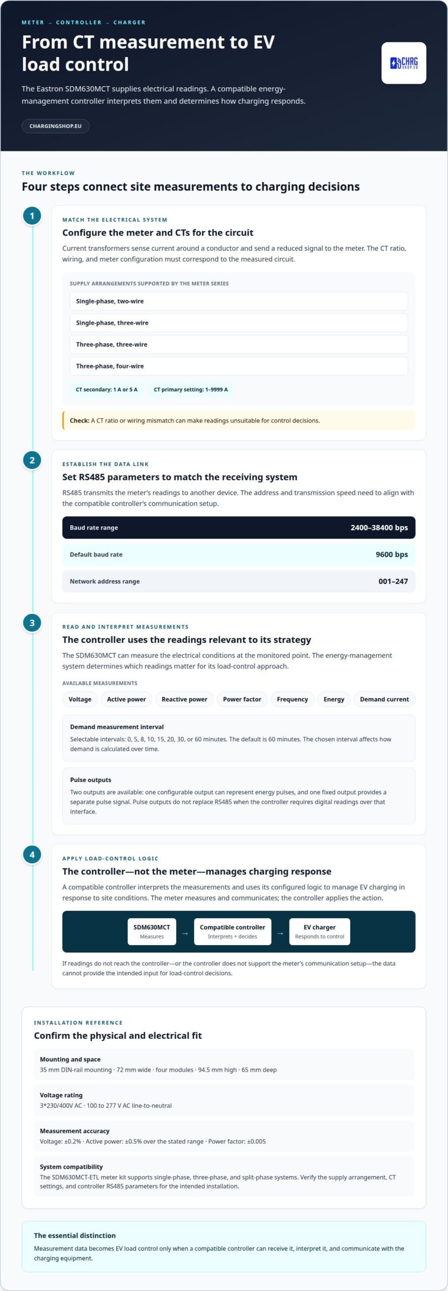
The SDM630MCT accepts CT secondary inputs of 1 A or 5 A. Its configurable CT primary-current settings run from 1 to 9999 A, allowing the meter configuration to reflect the selected transformer. The CT’s ratio and wiring must correspond to the measured circuit; an incorrect match can make readings unsuitable for control decisions.
The meter series supports four supply arrangements: single-phase two-wire, single-phase three-wire, three-phase three-wire, and three-phase four-wire. These configurations suit different electrical layouts and aren’t interchangeable. Identify your supply arrangement and choose the matching meter configuration so its phase measurements reflect the actual installation.
For example, a three-phase four-wire supply differs from a single-phase two-wire circuit. The meter’s configuration must match the conductors and CT placement. Accurate measurement is essential before a controller can use site demand as an input for EV load management.
Communication and control workflow
RS485 provides a way for the meter to transmit readings to another device. Its supported baud rates range from 2400 to 38400 bps, with 9600 bps as the default. Network addresses run from 001 to 247. These settings help identify the meter and establish communication on a shared network.
- Configure the meter for the supply type and CT ratio used on the circuit.
- Set the RS485 address and transmission speed to match the receiving system.
- Have the compatible controller read the relevant electrical measurements.
- Use the controller’s configured logic to manage EV charging in response to site conditions.
This process separates measurement from action. If readings don’t reach the controller, load-control decisions can’t use them. If the controller doesn’t support the meter’s communication setup, the data link won’t provide the intended input. Compatibility between the meter, controller, and charger is therefore central to the system design.
What the readings contribute
The SDM630MCT can measure voltage, active and reactive power, power factor, frequency, energy, and demand current. In an EV setup, a controller can use relevant readings to understand electrical conditions at the monitored point. The system’s control strategy determines which readings matter and how charging responds.
The meter also offers two pulse outputs. One configurable output can represent energy pulses, while the fixed output provides a separate pulse signal. These outputs can serve systems designed to receive pulse data, but they don’t replace the RS485 connection when a controller requires digital readings over that interface.
For demand measurement, the interval can be set to 0, 5, 8, 10, 15, 20, 30, or 60 minutes. The default interval is 60 minutes. A chosen interval affects how demand is calculated over time, so its relevance depends on the control system’s measurement and response approach.
Fit and configuration checks
The meter is designed for 35 mm DIN-rail mounting and measures 72 mm wide, occupying four modules. Its listed dimensions are 94.5 mm high and 65 mm deep. These measurements help establish whether the enclosure has room for the meter alongside CT wiring and communication connections.
Before relying on readings for EV load control, confirm three practical matches: the supply configuration, the CT secondary and primary settings, and the controller’s RS485 parameters. The SDM630MCT can provide measurement data; coordinated hardware and configuration turn that data into useful charging control.
The meter is rated for 3*230/400V AC and supports 100 to 277 V AC line-to-neutral. Its voltage measurement accuracy is ±0.2%, while active power measurement accuracy is ±0.5% over the stated range.
Power factor measurement accuracy is ±0.005. The SDM630MCT-ETL meter kit supports single-phase, three-phase, and split-phase systems, making system compatibility another point to verify alongside the selected CT configuration.
Charging Shop
Charging Shop helps you move from understanding meter-based load control to choosing EV charging hardware for your setup. The right charger depends on your charging requirements and the wider system it must work with. The meter alone doesn’t determine that choice.
For home or business charging plans, options include the V2C Trydan 22kW, V2C DENKA 20kW DC Wallbox, and Alfen Single Pro Line 22kW. If you’re weighing different requirements, a Personalised Charging Offer can help shape the hardware choice around your charging needs. Keep the meter, controller, and charger roles clear as you plan: each must fit the intended system.
Have questions about choosing charging hardware for your setup? Contact Charging Shop to discuss your requirements.
Plan Your Next Charging Step
Before choosing equipment, define what you want EV load control to achieve. Consider when vehicles need charging, how site demand should affect charging, and which system will coordinate the response. These priorities help turn meter readings into a practical charging plan, rather than treating the meter as a complete solution.
An Eastron SDM630MCT smart meter can be one part of that plan, but the wider setup needs to suit your electrical system and charging requirements. Focus on how the components will work together, and choose equipment with that complete picture in mind. A clear plan makes it easier to discuss the right direction for your home or business without assuming one configuration fits every site.
Contact Charging Shop for advice on your charging requirements and next step. Start planning with confidence.
